Globally Coupled Oscillations of Shallow Flow Past a Cavity
Submitted by bat310 on Wed, 2014-02-26 17:14
The structure of shallow flow past a cavity is characterized as a function of: elevation above the bed (bottom surface); and the onset of coupling between the separated shear layer along the opening of the cavity and a gravity wave mode within the cavity. A technique of particle image velocimetry is employed to characterize the flow structure. Coherent patterns of vorticity along the cavity opening and at the trailing (impingement) wall of the cavity are related to the streamline topology and associated critical points as a function of elevation above the bed. Associated patterns of normal and shear Reynolds stresses are defined, and related to the exchange velocity and mass exchange coefficient along the cavity opening. Substantial increase of mass exchange between the cavity and the main flow occurs in presence of shear layer-gravity wave coupling for all elevations above the bed.
Principal Investigators: B. A. Tuna & E. Tinar
Related Publication: Shallow flow past a cavity: globally coupled oscillations as a function of depth
Experiments were performed in a large-scale recirculating, free-surface water channel that has low free stream turbulence intensity (0.2%). A primary objective of this study is to determine the structure of a shallow, unsteady shear layer along the mouth of a cavity. Specifically, both non-coupled and fully coupled shear layer oscillations with the gravity wave mode of the cavity are of interest. A test section was designed to control the cavity dimensions, water depth, and flow velocity. The cavity section has a length L = 305 mm and a width W = 457 mm. A value of hw = 38.1 mm was employed in the present experiments; it was associated with the largest amplitude of the resonant-coupled oscillations of the free surface within the cavity. The amplitude of the gravity standing wave was hd = 3 mm which is shown in the plan view (section A-A) in Figure 1. This peak amplitude corresponds to a ratio of wave amplitude hd to the water depth hw of hd / hw = 0.078.
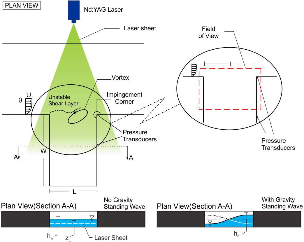
Figure 1. Schematic of experimental test section and quantitative imaging system. Also illustrated are unstable shear layer along the opening of the cavity and deformation of free surface due to the gravity standing wave within the cavity.
Figure 2 shows phase-averaged contours of constant vorticity <w>pL/U for three different phases of the oscillation cycle in presence of gravity standing wave. The left column of images represents the region well above the bed (zL/hw = 0.667) and the right column of images corresponds to the region near the bed (zL/hw = 0.067). At both zL/hw = 0.667 and 0.067, the patterns of <w>pL/U show the onset and development of a large-scale vortical structure. It moves in the downstream direction with increasing phase angle. At zL/hw = 0.667, the patterns of vorticity are highly ordered and do not show significant irregularities. On the other hand, at zL/hw = 0.067, notable distortions or irregularities occur; they are due to the decreased coherence of vortex formation along the bed region. Moreover, the cluster of vorticity that is along the trailing (impingement) wall of the cavity at zL/hw = 0.067 persists over all values of phase angle. On the other hand, this cluster of vorticity does not exist along the trailing (impingement) wall of the cavity at zL/hw = 0.667.
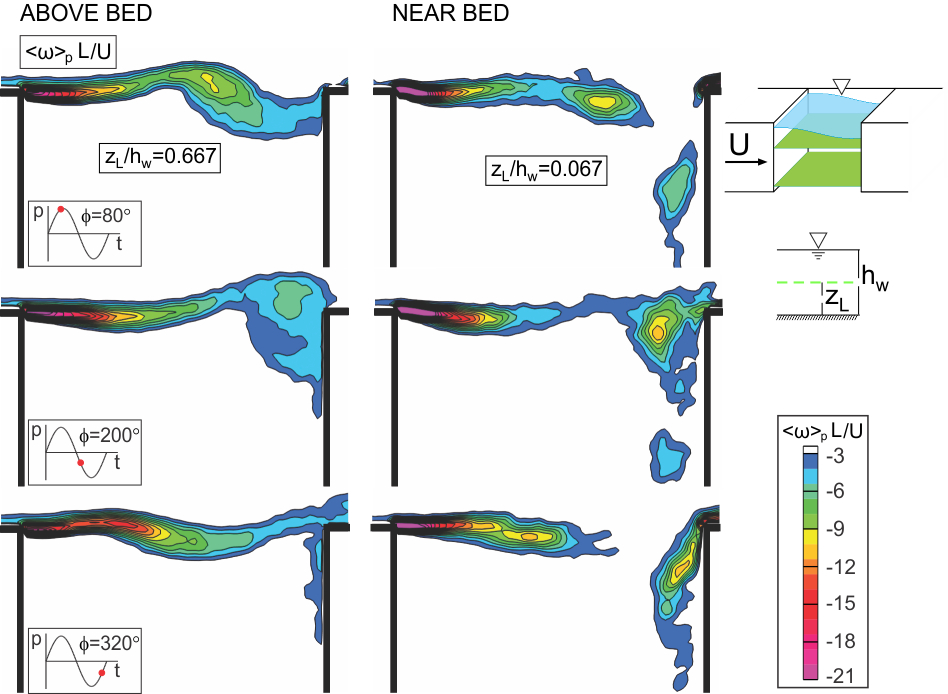
Figure 2. Contours of phase-averaged vorticity <w>pL/U at two different elevations: well above the bed (zL/hw = 0.667); and near the bed (zL/hw = 0.067) in presence of gravity standing wave.
Corresponding patterns of Reynolds stress <u′v′>/U 2 are given in Figure 3. In essence, the Reynolds stress represents the degree of correlation between the streamwise u′ and transverse v′ velocity fluctuations. This correlation is clearly high when the gravity standing wave exists, as shown in the top two figures in the right column of images, corresponding to elevations zL/hw = 0.500 and 0.333. As the bed region (zL/hw = 0.067) is approached, however, the peak value of Reynolds stress is significantly attenuated. Enhanced Reynolds stress increases the entrainment demand of the separated shear layer along the cavity. It is therefore anticipated that the mass exchange between the cavity and the free stream will be higher for the case where the standing wave occurs (right column of images, U/fnL = 1.44). Note that the magnitude of the Reynolds stress decreases as the bed is approached (zL/hw = 0.067). This observation suggests that the mass exchange will decrease as the bed region is approached.
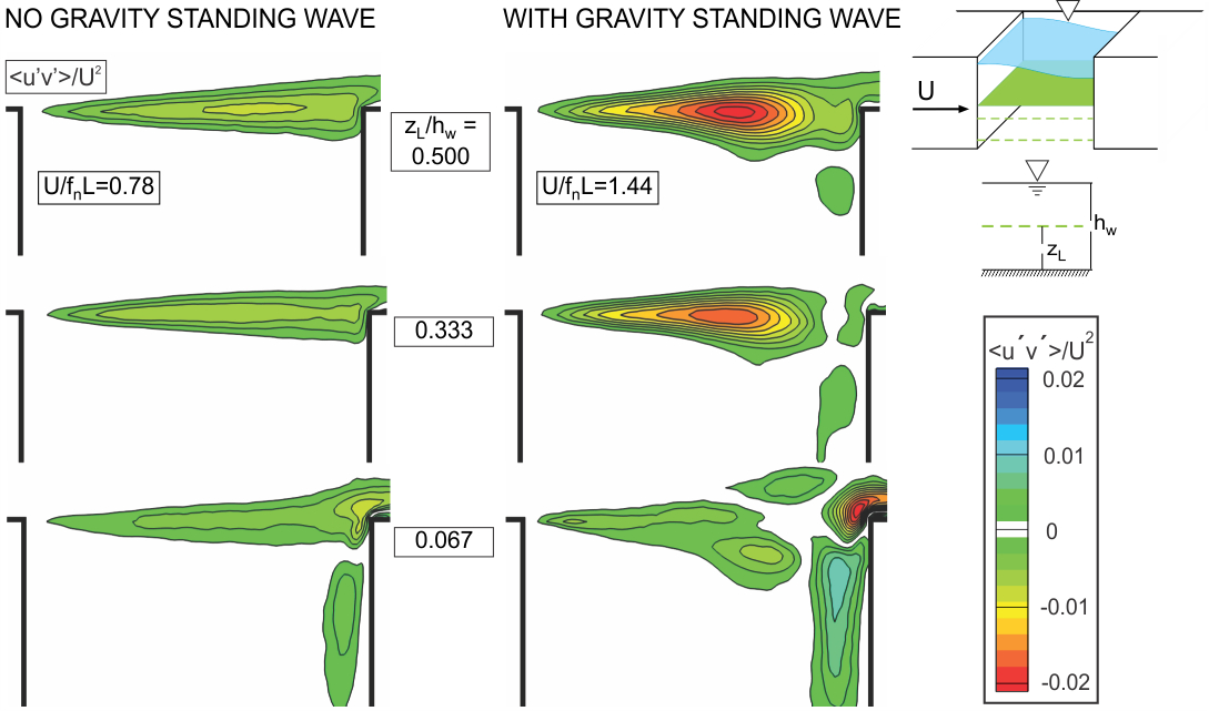
Figure 3. Pattern of Reynolds stress <u′v′>/U 2 at different elevations zL/hw above the bed.Dimensionless velocities U/fnL=0.78 (left column) and U/fnL=1.44 (right column) correspond, respectively, to cases without and with a gravity standing wave.
A dimensionless mass exchange coefficient k = <E(t)>/2U is employed, in accord with Weitbrecht et al. (2008), in order to characterize the mass exchange between the flow within and outside the cavity. Determination of this exchange coefficient requires, first of all, knowledge of the exchange velocity E. It is determined using the distribution of transverse velocity along the mouth of the cavity, which extends from the leading to the trailing corner of the cavity. Patterns of time-averaged exchange velocity <E(t)> are given in Figure 4. They were obtained by taking time averages over defined successive segments along the opening of the cavity, then connecting the time-averaged values. The left graph shows the case of no gravity standing wave (U/fnL=0.78) and the right graph shows the case where the gravity standing wave exists (U/fnL=1.44). The coordinate zL/hw represents, as in preceding figures, the elevation above the bed (bottom surface) and the x/L axis shows the streamwise location along the opening of the cavity. The blue point represents the leading edge (x/L=0) of the cavity and red point shows the trailing edge (x/L = 1) of the cavity. It is evident that the overall magnitudes of the exchange velocity are higher for the case corresponding to the coupled oscillation associated with the gravity standing wave. One can therefore deduce that the mass exchange coefficient k will be larger in presence of the gravity standing wave.
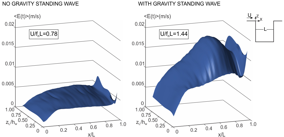
Figure 4. Patterns of time-averaged exchange velocity <E(t)> at different elevations zL/hw above the bed.Dimensionless velocities U/fnL=0.78 (left column) and U/fnL=1.44 (right column) correspond, respectively, to cases without and with a gravity standing wave.